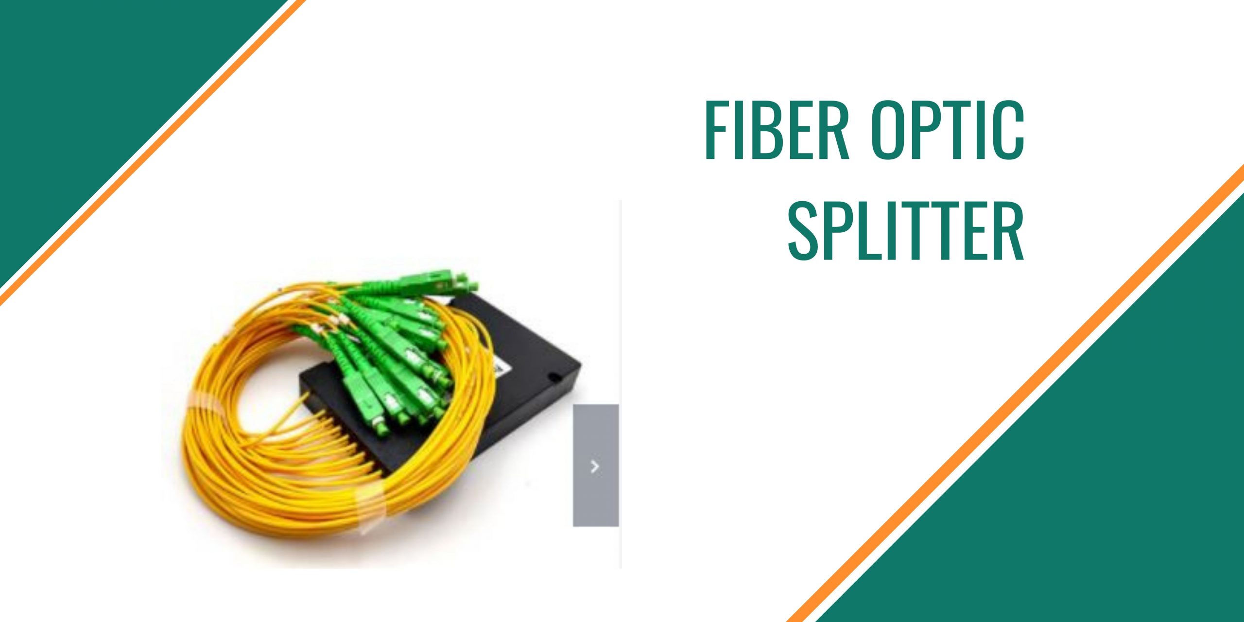
In total you will need to follow five different steps required to create fiber optic splitters. Each step requires strict supervision and control of different variables like temperature, environment and precise control of manufacturing and the equipment.
Step One: Preparation of Components
In general, three components are needed. It is the PLC circuit chips are placed in a glass wafer. Then, each edge on the glass wafer gets polished to guarantee a the most precise flat surface as well as high-purity. The v-grooves are then pressed on a glass substrate. A single or multiple ribbon fibers are then glued to the surface of the glass. Then, the assembly is polished.
Step Two Step Two: Alignment
Once the 3 components they are then placed on an alignment stage. The output and input fiber array is placed on a goniometer to be aligned to that of the PLC chip. The physical alignment between the fiber arrays as well as the chip is tracked by an ongoing power level output by the array of fibers.
3. Cure
The assembled piece is placed inside the room with a UV (ultraviolet) chamber, where it will cure completely at a temperature that is controlled.
Step Four Step Four: Step Four: Packaging
The splitter’s bare ends are placed in the metal housing, where fiber boots are placed at both ends of the structure. Then a testing of the temperature is necessary to verify the final quality.
5. Optical Testing
For testing purposes three crucial parameters like insertion loss, uniformity, and polarization dependent loss (PDL) are tested on the splitter in order to ensure that it is in line with the optical specifications of the splitter as per the GR-1209 CORE specifications.
How do you test the quality of a Fiber Optic Splitter?
The performance of an fiber optic splitter is mostly defined by five standards that include optical bandpass, loss of insertion, return loss as well as uniformity and directivity. This section explains how to test each one of the specifications.
1. The optical bandpass may be examined using an analyzer of optical spectrum using an extremely powerful light source with an axial wavelength that is the bandpass required. The attenuation of the bandpass must meet the requirements of the splitter.
2. The insertion loss is evaluated with an illumination source and a power meter. The power level of the reference source is determined and every input port on the optical splitter’s output is tested.
3. Return loss can be measured with the return loss meter. It is connected via the input ports to the return loss gauge. all outlets are linked to an non-reflective index match gel.
4. It is possible to determine the uniformity of an optical splitter could be assessed by looking at the results of the test of insertion loss to determine if the gap between the greatest loss and the smallest loss remains within the permissible range of uniformity.
5. The directivity test can be conducted using a method similar to the test for insertion loss. But, the power meter and light source are connected to the input ports, as well as the two outlets.
Conclusion
Fiber optic splitters allow the optical signal fiber to be spread across several fibers. Since splitters don’t contain any electronics and require no power and are not powered by electricity, they’re an essential element and are widely utilized in all fiber optical networks. So, selecting fiber optic splitters that help improve the efficiency for optical technology is essential to creating a network design that will last for the future. Read more.


